How a 3 phase motor control circuit works Electrical electronics robotics: plc Two wire & three wire motor control circuit
Electrical Electronics Robotics: PLC
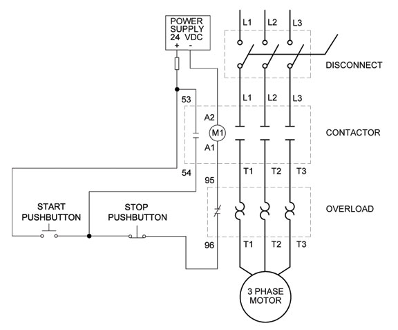
Wiring diagram: chapter 1.1. full-voltage non-reversing 3-phase motors
Auxiliary reversing rockwell latching voltage diagrams contactor eletrical ghisalba dol switches volt
Circuit control wire lamp three indicator wiring motor diagram ladder starter coil industrial when fig above energized added showCircuit stop start diagram motor control wire two three multiple wiring jog switch starter electrical electricala2z stations motors configuration gif Circuit control wire three start diagram motor button auxiliary industrial push seal contacts coil ladder connectedThree-wire control circuit with indicator lamp.
Wiring diagram: chapter 1.1. full-voltage non-reversing 3-phase motorsCircuits divided Wire motor control diagram circuit ladder basicsWiring controls.

Ladder diagram basics #3 (2 wire & 3 wire motor control circuit)
Motor button stop start diagram wiring starter circuit relay retain 480v control wire 120v push switch electrical symbol phase limit3 wire motor control Plc circuit ladder electrical motor control relay phase robotics electronics program above three3 wire motor control.
Wire circuit two control motor diagram three configuration gif electricalPhase motor circuit control works Three-wire control circuitTwo wire & three wire motor control circuit.