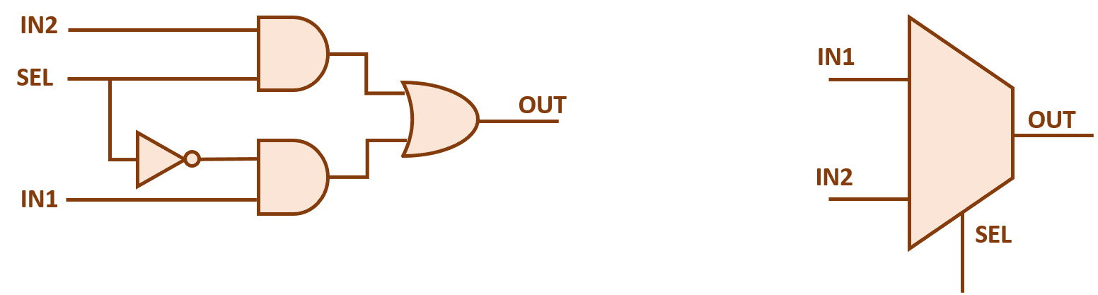
Solved: as shown, we are using 4:1 and 2:1 mux's to design... 2x1 mux multiplexer logic diagram schematic symbol vlsi using gates inverter input eda figure Mux verilog multiplexer using 2x1 4x2 diagram truth table if below
VHDL 4 to 1 MUX (Multiplexer)
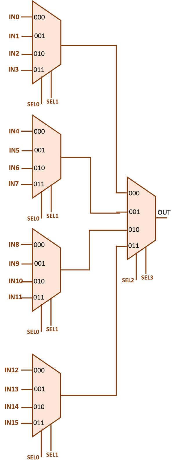
Mux 16 using multiplexers muxes 16x1 implementing help vlsi figure eda
Multiplexer mux using muxes implementation three digital configuration specific given uses shown below figure first
Mux 2x1 using 8x1 implementationMux diagram logic active high output multiplexers Mux using digital 16 multiplexers implement electronics general geeksforgeeks formula same usedDesign of 4×2 multiplexer using 2×1 mux in verilog.
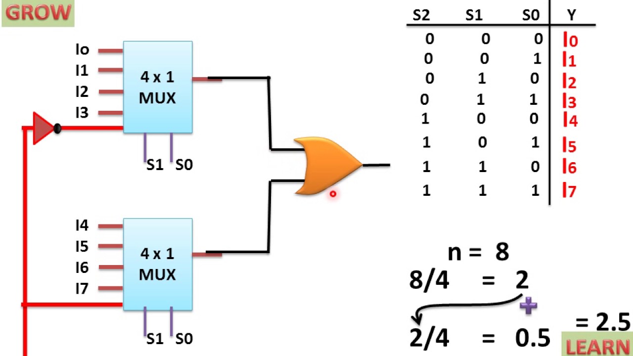
Implementation of 8x1 mux using 2x1 mux (हिन्दी )! learn and growMux multiplexer verilog 4x2 2x1 muxes block 41 mux logic diagram2x1 mux : vlsi n eda.

Mux using vhdl code structural shown write components case answer answers solved
Design 16 1 mux using 4 1 muxes : vlsi n eda8x1 mux multiplexer 4x1 logic implementation implement multiplexers logical 2x1 hardware Design of 4×2 multiplexer using 2×1 mux in verilog8x1 mux logic diagram : using 8 1 multiplexers to implement logical.
.