Combinational adder circuits 4 bit binary adder Adder bcd
😊 Four bit parallel adder. 4 bit Binary adder circuit / block diagram
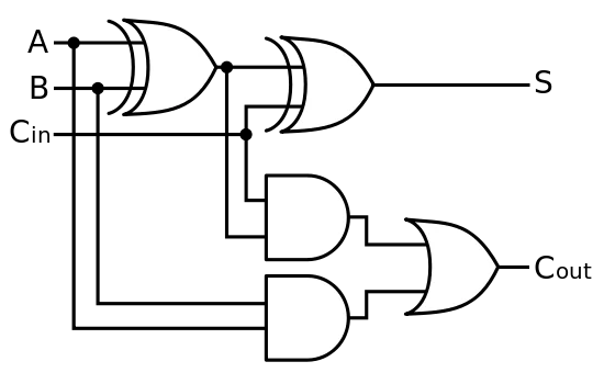
Digital logic design: full adder circuit
Adder bit logisim circuit using alu cs complement create unsigned lab1 labs courses cornell edu lab re ta sub ask
Adder logicCircuit adder bit diagram logic computing learn let Let's learn computing: 4 bit adder circuitDownload 4 bit adder circuit stick and logic diagram.
Adder bit ic datasheetAdder binary bit addition carry python will using bits input gates program sign ripple Adder bit parallel four circuit diagram binary subtractor logic digital block example geeksforgeeks detailed discussionAdder bit circuit subtractor carry ripple diagram logic using project build only computing learn let digital its indie electronics.

Full-adder circuit, the schematic diagram and how it works – deeptronic
11+ 4 bit adder circuit diagramBinary adder and binary addition using ex-or gates Dadda multiplierDownload 4 bit adder circuit stick and logic diagram.
Adder binary bit circuit truth table rtl example understand will need register use adders discuss detailsAdder circuit diagram schematic bit works figure Binary circuit output geeksforgeeks incrementedCd4008 4-bit full adder ic pinout, working, example and datasheet.

4 bit binary incrementer
Design a 4-bit combinational circuit decrementer using four full adderMultiplier adder dadda Adder subtractor binary circuit bit diagram coa logic block javatpoint modeLet's learn computing: 4 bit adder/subtractor circuit.
😊 four bit parallel adder. 4 bit binary adder circuit / block diagram .


